
Make two drivers work as one loudspeaker
Step by step: understand, predict, adjust and calculate.
01 · Find a shared operating range
Woofer and tweeter need a range where both can work properly. Frequency response, distortion, power handling and directivity all matter. A tweeter with low on-axis extension is not automatically suitable for a low crossover. This demo uses ideal drivers to explain summation first.
02 · Put levels on the same basis
Compare measurements only at the same distance and drive condition. 2.83 V is about 1 W into 8 Ω but about 2 W into 4 Ω. A difference caused by unlike references is not a valid sensitivity comparison. Passive matching usually attenuates the louder branch.
03 · Electrical filters are only one part
Acoustic transfer combines driver response with electrical filtering. Any natural driver roll-off contributes too. A fourth-order electrical filter therefore does not automatically create a fourth-order acoustic slope. Define the acoustic target first, then compare the measured complete branch with it.
04 · Two half amplitudes can add to one
At an ideal LR4 crossover, each branch has half amplitude at crossover, approximately −6 dB relative to its passband. With matching phase, those amplitudes add to full level. You do not add their dB values directly. The complex signals must be summed.
05 · A few centimetres change phase
Extra path length creates frequency-dependent delay. At 2 kHz, 0.25 ms is half a period, or 180°. The ideal example develops a deep cancellation at crossover. At 343 m/s this corresponds to about 8.6 cm extra path. Reversing polarity instead changes sign at all frequencies; it is not a universal delay correction.
06 · Measure the completed system
Measure each filtered branch separately, then both together. Keep position and time reference unchanged. Check the crossover region, impedance and off-axis behaviour. A good on-axis sum is an important step, but not a complete assessment of sound, power handling or directivity.
Workshop takeaway
Level, phase and operating range must agree. Two good individual drivers become a good team through a suitable crossover.
Work it out · answers unfold
Write down your prediction first, then your calculation. Open the answer only when you are ready to compare.
01 · A woofer gives 88 dB and a tweeter 92 dB at the same operating point and reference. What level correction is an initial estimate?
Show worked answer
- Difference: 92 - 88 = 4 dB.
- Initially attenuate tweeter by 4 dB.
- Then measure crossover region.

02 · A 4 Ω driver is measured at 2.83 V. What is electrical power for a purely resistive substitute?
Show worked answer
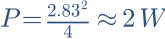
- P = U²/R.
- 2.83²/4 = 2.002 W.
- Here 2.83 V means about 2 W, not 1 W.
03 · How do you ideally convert 90 dB at 2.83 V/1 m with 4 Ω to 1 W/1 m?
Show worked answer
- Initial power is about 2 W.
- Half power reduces level by 3.01 dB.
- Result about 87 dB/1 W/1 m.

04 · Sound speed 343 m/s, frequency 1 kHz. Find wavelength.
Show worked answer
- Wavelength = speed/frequency.
- 343/1000.
- Wavelength = 0.343 m = 34.3 cm.

05 · Two sound paths differ by 3.43 cm. Calculate delay difference.
Show worked answer
- Path difference in m: 0.0343.
- Delay = distance/speed.
- Delay = 0.1 ms.

06 · What phase difference does 0.1 ms create at 1 kHz?
Show worked answer
- Period is 1 ms.
- 0.1 ms is one tenth of a cycle.
- Magnitude: 36°. Delayed branch lags.

07 · Calculate the same delay-induced phase difference at 3 kHz.
Show worked answer
- Frequency triples.
- Phase magnitude triples.
- 108°.

08 · Two equally strong coherent signals of pressure ratio 1 are in phase. Find sum level relative to one signal.
Show worked answer
- Add pressure ratios: 2.
- 20 log10(2).
- Sum is 6.02 dB above one signal.

09 · The same equal signals differ by 180°. What does the ideal model predict at this measurement point?
Show worked answer
- One signal has opposite sign.
- 1 + (-1) = 0.
- Complete cancellation; real systems usually retain some residual.
10 · Two signals of pressure ratio 1 have 90° phase difference. Find summed magnitude.
Show worked answer
- Add perpendicular components quadratically.
- Magnitude = √2.
- Relative to one signal: +3.01 dB.

11 · LR4 crossover: both branches have pressure ratio 0.5 but differ by 90°. How far below target 1 is the sum?
Show worked answer
- Magnitude = √(0.5² + 0.5²) = 0.7071.
- 20 log10(0.7071).
- Sum is 3.01 dB below target.

12 · One branch reaches the microphone 0.2 ms earlier. Which branch should be delayed for time alignment?
Show worked answer
- Delay the earlier branch.
- Added delay: 0.2 ms.
- Check crossover region afterward; acoustic centres are not always constant.
13 · Why does polarity inversion not replace a fixed time delay across all frequencies?
Show worked answer
- Polarity inversion gives 180° at all frequencies.
- Delay-induced phase grows with frequency.
- They can coincide only at particular frequencies.

14 · Driver centres are 17 cm apart. At what frequency does this equal one wavelength, c = 343 m/s?
Show worked answer
- Distance in m: 0.17.
- f = c/d.
- f = 2017.65 Hz; this alone does not define a safe crossover.

15 · Why is a smooth on-axis response insufficient for selecting drivers?
Show worked answer
- Horizontal and vertical radiation may be discontinuous.
- Room reflections contain off-axis energy.
- Check multiple angles, distortion and power handling.
16 · A woofer has strong breakup above 3 kHz; a tweeter is only sufficiently robust above 4 kHz. What is the problem?
Show worked answer
- There is no obvious clean usable overlap.
- Do not simply choose a midpoint.
- Consider another driver pairing or add a midrange.
17 · A midwoofer needs 1 mm excursion at 100 Hz. Estimate excursion at 50 Hz for the same SPL in the simple piston model.
Show worked answer
- Excursion is approximately inversely proportional to frequency squared.
- Half frequency requires four times excursion.
- Result: 4 mm; enclosure effects excluded here.

18 · Two identical 8 Ω drivers are wired in parallel. Find nominal load and effect on amplifier current at the same voltage.
Show worked answer
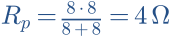
- Nominal equivalent: 4 Ω.
- At constant voltage total current doubles in the resistive model.
- Check amplifier capability and actual impedance curve.
19 · Why must separately measured driver phases not be arbitrarily reset to zero when predicting their sum?
Show worked answer
- Relative timing determines phase difference.
- Independent shifts remove real delay differences.
- Use a shared time reference or correctly restore known offsets.
20 · Put a two-way design workflow in order: level, driver data, branches, sum, angles and loading.
Show worked answer
- Measure installed drivers with impedance and shared timing.
- Check overlap, choose targets, filter branches and match levels.
- Verify complex sum; check angles, impedance and loading, then iterate.
Further reading
Original teaching models and authored exercises. Sources provide technical background; no manufacturer measurement curves are reproduced.