
The mental picture
At a particular frequency, the model provides an especially easy shunt path. Less voltage then remains at the output. This describes the series RLC branch to ground shown here, fed through a series resistor.
The principle
A series resonator has low impedance at resonance and can act as a shunt trap. A parallel resonator has high impedance there and can act as a series blocking network. Both can create notches, but their circuits and equations are not interchangeable.
Try it yourself
Notch networks & resonant traps
Change C first: the notch moves. Then change only damping resistance R: notch depth changes. Frequency and strength are separate design tasks.
Model limits: Unloaded output across a series RLC shunt branch, fed through Rs. Not a complete loudspeaker trap network.
A worked example
1 mH and 2.2 µF resonate around 3.39 kHz. With Rs = 10 Ω and R = 3 Ω, the resonant voltage ratio is 3/13, about −12.7 dB.
A closer look · equations and assumptions
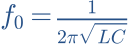

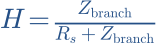
This teaching model has an unloaded output. A real driver in parallel with the branch changes the calculation. Across an ideal source with no series impedance, a shunt branch cannot reduce source voltage; it only draws more current. That is why Rs cannot silently disappear from this model.
A common pitfall. Building a notch from a datasheet frequency without measuring the driver in its own baffle may miss the actual problem.
Workshop takeaway
Measure the problem first, then target frequency, width and depth. Apply only the correction needed and verify the complete result.
Sources & transparency
Original illustrations and educational calculations. No measurements of a specific product. Edited 11 October 2026.
Work it out · answers unfold
Write down your prediction first, then your calculation. Open the answer only when you are ready to compare.
15 · A series RLC branch has L = 1 mH and C = 10 µF. Find resonance frequency.
Show worked answer
- L · C = 10⁻⁸.
- Square root = 0.0001.
- Resonance = 1591.55 Hz.

16 · How do you move this resonance to half frequency while retaining L?
Show worked answer
- Resonance is inversely proportional to square root of C.
- Quadruple C for half frequency.
- New C = 40 µF.

17 · A measured peak at 2 kHz is 4 dB above target. What voltage ratio is needed for ideal local correction?
Show worked answer
- Correction is -4 dB.
- Ratio = 10^(-4/20).
- Ratio = 0.6310; bandwidth and phase must also fit.

18 · A deep dip comes from opposite-phase sound contributions. Why is strong EQ boost usually a poor first fix?
Show worked answer
- Cancellation remains.
- More drive increases excursion and power.
- First check polarity, delay, geometry and individual branches.