
The mental picture
As frequency rises, voice-coil inductance makes the electrical load harder to drive. A parallel RC branch increasingly provides another current path. With the matching ideal model, the source sees a more uniform total load.
The principle
A Zobel consists of a resistor and capacitor in series, with that whole branch connected across the driver. The capacitor is not simply shorted across the amplifier. The resistor is essential to this function.
Try it yourself
The Zobel network
Increase Le at fixed Re. The uncompensated impedance rise grows and the proposed capacitance rises. The corrected curve remains exactly flat only because the model and network match exactly.
Model limits: Driver represented only by Re plus Le, with no mechanical resonance. Exactly matched ideal RC branch.
A worked example
For Re = 6 Ω and Le = 0.5 mH, the simple model gives Rz = 6 Ω and Cz ≈ 13.9 µF. This is a starting value for an ideal electrical model, not an unchecked construction recommendation.
A closer look · equations and assumptions




Substitution gives Ztotal = Re for the ideal Re–Le model. Real voice coils often have frequency-dependent inductive losses, and mechanical resonance is absent here. A Zobel therefore does not remove every impedance peak or flatten the acoustic response.
A common pitfall. The Zobel resistor can dissipate power. Lower total impedance can place additional load on the amplifier.
Workshop takeaway
Use it when crossover development calls for it, not simply because a crossover with more parts looks more professional.
Sources & transparency
Original illustrations and educational calculations. No measurements of a specific product. Edited 11 October 2026.
Work it out · answers unfold
Write down your prediction first, then your calculation. Open the answer only when you are ready to compare.
06 · An ideal series inductor feeds a purely resistive 8 Ω substitute driver. Target first-order electrical low-pass at 2 kHz. Find L.
Show worked answer
- At cutoff, inductive reactance equals R.
- L = R/(2πfc).
- L = 0.637 mH.

09 · A speaker has 8 Ω nominal impedance. Why is task 6 not a complete real crossover design?
Show worked answer
- Impedance varies with frequency and is complex.
- The acoustic driver response also contributes.
- Include measured magnitude, phase and mounting geometry.
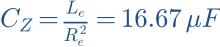
13 · Idealised driver: Re = 6 Ω, Le = 0.6 mH. Find Zobel R and C for the Re-plus-Le model.
Show worked answer
- Zobel R = Re = 6 Ω.
- Zobel C = Le/Re².
- C = 16.67 µF. This model has no mechanical resonance.
14 · Which is correct: a Zobel automatically flattens sound pressure, or it first compensates an impedance rise?
Show worked answer
- First, impedance compensation.
- This can make the preceding crossover behave more predictably.
- Acoustic flatness is not guaranteed.
20 · Plan a fair before-and-after test of a crossover correction. Name four conditions.
Show worked answer
- Same measurement position and excitation.
- Measure branches and sum with timing preserved.
- Check impedance and multiple angles; use identical smoothing.