
The mental picture
Some electrical energy becomes heat rather than useful sound. An L-pad distributes that task between a series and a shunt resistor. In the ideal model it maintains constant input resistance while reducing driver voltage.
The principle
The series resistor lies in the signal path. The shunt resistor connects directly across the load. This design assumes a purely resistive load and keeps input resistance equal to that load value. A single series resistor behaves differently.
Try it yourself
Level matching with an L-pad
Compare 3, 6 and 12 dB attenuation. Watch resistor values and how much input power is dissipated by the two resistors together.
Model limits: Ideal L-pad into a resistive load. No frequency-dependent driver impedance or heating model.
A worked example
For 6 dB into 8 Ω, values are approximately 3.99 Ω series and 8.04 Ω shunt. Load voltage ratio is about 0.501, so only about one quarter of input power reaches the resistive load.
A closer look · equations and assumptions
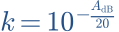

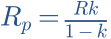
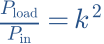
For this design, PRs/Pin = 1−k and PRp/Pin = k(1−k). This lets you assess heating separately. With frequency-dependent driver impedance, attenuation is not exactly constant. Placing the pad before or after a filter also changes loading.
A common pitfall. The plotted power is an electrical model quantity, not a direct music-power rating for a particular resistor.
Workshop takeaway
Match levels, then measure the whole crossover again. A correctly calculated L-pad does not guarantee the right acoustic transition.
Sources & transparency
Original illustrations and educational calculations. No measurements of a specific product. Edited 11 October 2026.
Work it out · answers unfold
Write down your prediction first, then your calculation. Open the answer only when you are ready to compare.
10 · A branch should be attenuated by 6 dB in voltage magnitude. Find the ratio.
Show worked answer
- Convert dB back to voltage ratio.
- k = 10^(-6/20).
- k = 0.5012.

11 · Constant-input-resistance L-pad: load 8 Ω, k = 0.5. Find series and shunt resistors. Shunt is across load.
Show worked answer
- Series R = R(1-k) = 4 Ω.
- Shunt R = Rk/(1-k) = 8 Ω.
- 8 Ω parallel 8 Ω = 4 Ω, plus 4 Ω = 8 Ω.

12 · The L-pad in task 11 receives 8 V. Find load power and both resistor dissipations.
Show worked answer
- Source current = 8/8 = 1 A.
- Series resistor: 4 W; output: 4 V.
- Load and shunt resistor each dissipate 2 W.

17 · A measured peak at 2 kHz is 4 dB above target. What voltage ratio is needed for ideal local correction?
Show worked answer
- Correction is -4 dB.
- Ratio = 10^(-4/20).
- Ratio = 0.6310; bandwidth and phase must also fit.
