
The mental picture
A swing alternates between kinetic and potential energy. An LC system exchanges energy between magnetic and electric fields. Losses damp the exchange, but suitable external excitation can still create a large response.
The principle
In a series RLC circuit, inductor and capacitor reactances have opposite signs. At resonance they cancel in the total impedance, leaving only R to limit current in the ideal model. This does not mean the voltages across L and C are zero.
Try it yourself
RLC & resonance
Reduce R at fixed L and C. Resonance frequency stays the same, but the current peak becomes taller and narrower.
Model limits: Ideal series RLC circuit driven by a sine. Frequency axis spans f0/10 to 10f0; all losses are represented by R.
A worked example
10 mH and 10 µF resonate at about 503 Hz. With 10 Ω and 5 V RMS, resonant current is 0.5 A. Q is about 3.16; voltages across the reactive components can exceed source voltage.
A closer look · equations and assumptions
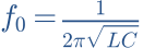



For the series circuit, half-power bandwidth is Δf = R/(2πL), giving Q = f0/Δf. Other topologies have different Q relationships. A parallel resonator can have high input impedance at resonance. “Resonance” alone does not tell you whether current peaks or dips.
A common pitfall. Do not confuse series and parallel arrangements. Low resistive loss can allow large resonant currents and voltages.
Workshop takeaway
Resonance is a tool, not a quality badge. Frequency, damping and where the output is taken determine its effect.
Sources & transparency
Original illustrations and educational calculations. No measurements of a specific product. Edited 11 October 2026.
Work it out · answers unfold
Write down your prediction first, then your calculation. Open the answer only when you are ready to compare.
13 · Idealised driver: Re = 6 Ω, Le = 0.6 mH. Find Zobel R and C for the Re-plus-Le model.
Show worked answer
- Zobel R = Re = 6 Ω.
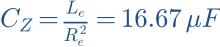
- Zobel C = Le/Re².
- C = 16.67 µF. This model has no mechanical resonance.
15 · A series RLC branch has L = 1 mH and C = 10 µF. Find resonance frequency.
Show worked answer
- L · C = 10⁻⁸.
- Square root = 0.0001.
- Resonance = 1591.55 Hz.

16 · How do you move this resonance to half frequency while retaining L?
Show worked answer
- Resonance is inversely proportional to square root of C.
- Quadruple C for half frequency.
- New C = 40 µF.

17 · A measured peak at 2 kHz is 4 dB above target. What voltage ratio is needed for ideal local correction?
Show worked answer
- Correction is -4 dB.
- Ratio = 10^(-4/20).
- Ratio = 0.6310; bandwidth and phase must also fit.
