
RC low-pass: measure across C
Across which component is output measured?
Hint
Follow M and B.
Answer and working
Across C1. Choosing this output makes the arrangement a low-pass filter.
What do you expect at very low frequency?
Hint
Capacitive reactance rises as frequency falls.
Answer and working
Almost the full input appears across C1: Uout approaches 1 V peak.
Calculate cutoff frequency.
Hint
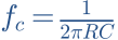
100 nF = 0.0000001 F; fc = 1/(2πRC).
Answer and working
Calculation notes


What are output amplitude and phase at fc?
Hint
Magnitude is 1/√2; a low-pass has negative phase.
Answer and working
Calculation notes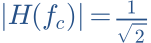



The voltage is not half of the input here.
Double C1. Where does fc move? Check the filter model.
Hint
fc is inversely proportional to C.
Answer and working
Calculation notes


This calculation assumes no additional output load.
Think it through before opening the answer. Always write the formula, substituted values and units.
RC high-pass: measure across R
Across which component is output measured?
Hint
Follow M and B.
Answer and working
Across R1. R and C have swapped positions compared with the low-pass.
What output remains for a constant DC input?
Hint
After charging, no DC flows through the ideal capacitor.
Answer and working
Calculation notes

This applies at steady state. A transient output may appear at switch-on.
Calculate fc.
Hint
fc = 1/(2πRC), regardless of which component is below.
Answer and working
Calculation notesThe same cutoff does not mean the same response.
Find amplitude and phase at fc.
Hint
Magnitude is 1/√2; high-pass output leads.
Answer and working
Calculation notes

Compare high-pass and low-pass at 10 × fc.
Hint
High-pass: x/√(1+x²); low-pass: 1/√(1+x²), x=f/fc.
Answer and working
Calculation notes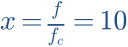




Compare both model curves near 15.9 kHz.
Think it through before opening the answer. Always write the formula, substituted values and units.
The mental picture
Think of two paths whose relative ease changes with speed. In an RC network, frequency changes the voltage division between resistor and capacitor. Transitions are gradual; frequencies are not cut off with scissors.
The principle
An RC low-pass takes output across the capacitor. An RC high-pass places the capacitor in series and takes output across the resistor. A band-pass combines lower and upper limits. Unbuffered stages load each other.
Try it yourself
High-pass, low-pass & band-pass
Increase C. Both corner frequencies move down, but the curves pass opposite frequency ranges.
Model limits: Separately evaluated ideal RC high-pass and low-pass filters with unloaded outputs. Not a physical cascade.
A worked example
10 kΩ and 0.1 µF give a corner frequency of about 159 Hz. Both ideal outputs have 70.7% voltage magnitude there. You cannot simply add their dB values or magnitudes because their phases differ.
A closer look · equations and assumptions


A first-order filter has an asymptotic slope of 20 dB per decade, about 6 dB per octave. Cascaded transfer functions multiply rather than add. That applies to suitably isolated stages; mutual loading requires solving the complete circuit.
A common pitfall. Two RC stages in sequence do not automatically form an arbitrary Butterworth or Linkwitz–Riley filter. Order, damping and loading conditions belong together.
Workshop takeaway
Always specify where the output is taken. Understand the basic circuit before assembling higher orders.
Sources & transparency
Original illustrations and educational calculations. No measurements of a specific product. Edited 11 October 2026.
Work it out · answers unfold
Write down your prediction first, then your calculation. Open the answer only when you are ready to compare.
01 · RC low-pass: R = 1 kΩ, C = 100 nF. Find cutoff with ideal source and unloaded output across C.
Show worked answer
- RC = 0.0001 s.
- Cutoff = 1/(2πRC).
- Cutoff = 1591.55 Hz.

02 · What voltage ratio and dB value does this low-pass have at cutoff?
Show worked answer
- Ratio = 1/√2 = 0.7071.
- 20 log10(0.7071).
- Result: -3.01 dB.

03 · Find this low-pass voltage ratio at ten times cutoff.
Show worked answer
- Frequency ratio: 10.
- Ratio = 1/√(1 + 10²).
- 0.0995 or -20.04 dB.

04 · You want to halve the RC low-pass cutoff while retaining R. What changes?
Show worked answer
- Cutoff is inversely proportional to C.
- Double capacitance.
- 100 nF becomes 200 nF.
