Skip to content
LNGR SPKRHIFI. TWO WAYS. HANDCRAFTED.
LNGR · Circuit workshop

Read circuits. Step by step.

Ten simple circuits, fifty small tasks. Begin with one current loop and work towards filters. Each answer stays hidden until you need it.

How to read these drawings

Lines are wires. Black dots mark electrical junctions. R denotes resistors, C capacitors, L inductors and D diodes. A, B and M are test points, not additional components. B is our 0 V reference, not automatically protective earth or ground.

UAB means voltage at A relative to B. A voltmeter connects in parallel: red probe at A, black at B. An ammeter instead goes in series in an opened current path; it does not connect directly across a voltage source.

These begin as paper and model exercises with ideal components. For a physical build, use a current-limited low-voltage source and check component values, polarity and ratings. The sine source is a small signal, not mains voltage.

  1. A closed circuit
  2. Two resistors in series
  3. Two parallel current paths
  4. Dividing voltage — with a load
  5. An LED with a series resistor
  6. The diode as a current valve
  7. Charging a capacitor
  8. An inductor builds up current
  9. RC low-pass: measure across C
  10. RC high-pass: measure across R
Circuit 01 · 5 small steps

A closed circuit

Read circuits. Step by step. | LNGR SPKRThe ideal DC source holds A at +5 V relative to B. Wires are ideal. One resistor closes the loop. Conventional current flows externally from A through R1 to B.+−5 VAB · 0 VR1 = 1 kΩ
The ideal DC source holds A at +5 V relative to B. Wires are ideal. One resistor closes the loop. Conventional current flows externally from A through R1 to B.
  1. Trace the current path. Where does it return?

    Hint

    The source needs a closed external circuit.

    Answer and working

    From A through R1 to B and back to the source. Current is not used up in the resistor; electrical energy becomes heat.

  2. What voltage is measured between A and B?

    Hint

    The probes are connected across the resistor.

    Answer and working
    Calculation notes


    U_{AB}=+5\,\mathrm{V}
    U_{BA}=-5\,\mathrm{V}

    Probe polarity determines the sign.

  3. Convert 1 kΩ to Ω and calculate I.

    Hint

    I = U/R; 1 kΩ = 1000 Ω.

    Answer and working
    Calculation notes

    R=1\,\mathrm{k\Omega}=1000\,\Omega
    I=\frac{U}{R}
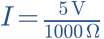
    I=\frac{5\,\mathrm{V}}{1000\,\Omega}
    {I=0.005\,\mathrm{A}=5\,\mathrm{mA}}
  4. How much power does R1 dissipate?

    Hint

    P = U × I. Use amperes for current.

    Answer and working
    Calculation notes
    P=U\cdot I
    P=5\,\mathrm{V}\cdot0.005\,\mathrm{A}
    {P=0.025\,\mathrm{W}=25\,\mathrm{mW}}
  5. Imagine doubling R1 to 2 kΩ. What happens? Check the model.

    Hint

    The source keeps U constant.

    Answer and working
    Calculation notes

    I=\frac{5\,\mathrm{V}}{2000\,\Omega}=2.5\,\mathrm{mA}
    P=5\,\mathrm{V}\cdot0.0025\,\mathrm{A}
    {P=12.5\,\mathrm{mW}}

    At fixed voltage, doubling resistance halves current and power.

Think it through before opening the answer. Always write the formula, substituted values and units.

Open the related article and interactive model →

Circuit 02 · 5 small steps

Two resistors in series

Read circuits. Step by step. | LNGR SPKRR1 and R2 are connected in series. M is their junction. No additional load is connected at M. B is the 0 V reference.+−9 VAB · 0 VR1 = 1 kΩR2 = 2 kΩM
R1 and R2 are connected in series. M is their junction. No additional load is connected at M. B is the 0 V reference.
  1. Are there one or two paths from A to B?

    Hint

    Look for a branch.

    Answer and working

    There is exactly one path. Both resistors carry the same current.

  2. Calculate the total resistance.

    Hint

    Series resistances add.

    Answer and working
    Calculation notes
    R_{\mathrm{total}}=R_1+R_2
    R_{\mathrm{total}}=1000\,\Omega+2000\,\Omega
    {R_{\mathrm{total}}=3000\,\Omega=3\,\mathrm{k\Omega}}
  3. Find the current through R1 and R2.

    Hint

    Use the full source voltage and total resistance.

    Answer and working
    Calculation notes
    I=\frac{U}{R_{\mathrm{total}}}
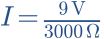
    I=\frac{9\,\mathrm{V}}{3000\,\Omega}
    {I_1=I_2=3\,\mathrm{mA}}
  4. Find UAM and UMB.

    Hint

    For each resistor, U = R × I.

    Answer and working
    Calculation notes
    U_{AM}=R_1\cdot I
    U_{AM}=1000\,\Omega\cdot0.003\,\mathrm{A}=3\,\mathrm{V}
    U_{MB}=2000\,\Omega\cdot0.003\,\mathrm{A}=6\,\mathrm{V}
    {U_{AM}+U_{MB}=3\,\mathrm{V}+6\,\mathrm{V}=9\,\mathrm{V}}
  5. What do red at M and black at B read? What if R1 and R2 swap places?

    Hint

    You measure across the lower resistor only.

    Answer and working
    Calculation notes
    U_{MB}=6\,\mathrm{V}
    R_1\leftrightarrow R_2
    U_{MB}=1000\,\Omega\cdot0.003\,\mathrm{A}
    {U_{MB}=3\,\mathrm{V}}

    After swapping, the smaller resistor is below. Total current stays the same.

Think it through before opening the answer. Always write the formula, substituted values and units.

Open the related article and interactive model →

Circuit 03 · 5 small steps

Two parallel current paths

Read circuits. Step by step. | LNGR SPKRBoth resistors connect to the same nodes A and B. Black dots mark connected wires. The source maintains 6 V.+−6 VAB · 0 VR2 = 2 kΩR1 = 1 kΩ
Both resistors connect to the same nodes A and B. Black dots mark connected wires. The source maintains 6 V.
  1. What is the voltage across each resistor?

    Hint

    Their terminals connect to the same two nodes.

    Answer and working
    Calculation notes
    {U_{R1}=U_{R2}=U_{AB}=6\,\mathrm{V}}

    Voltage does not split here.

  2. Calculate current in the first branch.

    Hint

    I1 = U/R1.

    Answer and working
    Calculation notes
    I_1=\frac{U}{R_1}
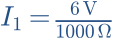
    I_1=\frac{6\,\mathrm{V}}{1000\,\Omega}
    {I_1=0.006\,\mathrm{A}=6\,\mathrm{mA}}
  3. Calculate current in the second branch.

    Hint

    I2 = U/R2.

    Answer and working
    Calculation notes
    I_2=\frac{U}{R_2}
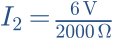
    I_2=\frac{6\,\mathrm{V}}{2000\,\Omega}
    {I_2=0.003\,\mathrm{A}=3\,\mathrm{mA}}
  4. How much current must the source supply?

    Hint

    Branch currents add at the node.

    Answer and working
    Calculation notes
    I_{\mathrm{total}}=I_1+I_2
    I_{\mathrm{total}}=6\,\mathrm{mA}+3\,\mathrm{mA}=9\,\mathrm{mA}
    R_{\mathrm{total}}=\frac{U}{I_{\mathrm{total}}}
    {R_{\mathrm{total}}=\frac{6\,\mathrm{V}}{0.009\,\mathrm{A}}\approx667\,\Omega}
  5. R2 is disconnected. Does current in R1 increase?

    Hint

    The ideal source still maintains 6 V.

    Answer and working
    Calculation notes
    I_2=0
    I_1=\frac{6\,\mathrm{V}}{1000\,\Omega}=6\,\mathrm{mA}
    {I_{\mathrm{total}}=6\,\mathrm{mA}}

    Current in the first branch stays the same. Only total current falls.

Think it through before opening the answer. Always write the formula, substituted values and units.

Open the related article and interactive model →

Circuit 04 · 5 small steps

Dividing voltage — with a load

Read circuits. Step by step. | LNGR SPKRThe two resistors represent a 10 kΩ potentiometer at its midpoint. M is the wiper. Initially, the M–B output is unloaded.+−5 VAB · 0 VR1 = 5 kΩR2 = 5 kΩR_L10 kΩM
The two resistors represent a 10 kΩ potentiometer at its midpoint. M is the wiper. Initially, the M–B output is unloaded.
  1. What is the resistance between A and B?

    Hint

    Add R1 and R2.

    Answer and working
    Calculation notes
    R_{\mathrm{total}}=R_1+R_2
    {R_{\mathrm{total}}=5\,\mathrm{k\Omega}+5\,\mathrm{k\Omega}=10\,\mathrm{k\Omega}}
  2. What current flows through the unloaded divider?

    Hint

    I = 5 V / 10,000 Ω.

    Answer and working
    Calculation notes
    I=\frac{U}{R_{\mathrm{total}}}
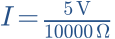
    I=\frac{5\,\mathrm{V}}{10000\,\Omega}
    {I=0.0005\,\mathrm{A}=0.5\,\mathrm{mA}}
  3. What is the output voltage between M and B?

    Hint

    UMB = I × R2.

    Answer and working
    Calculation notes
    U_{MB}=I\cdot R_2
    U_{MB}=0.0005\,\mathrm{A}\cdot5000\,\Omega
    {U_{MB}=2.5\,\mathrm{V}}
  4. Now connect RL = 10 kΩ between M and B. Find R2 parallel RL.

    Hint

    Rparallel = R2 × RL / (R2 + RL).

    Answer and working
    Calculation notes
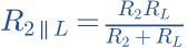
    R_{2\parallel L}=\frac{R_2R_L}{R_2+R_L}
    R_{2\parallel L}=\frac{5\,\mathrm{k\Omega}\cdot10\,\mathrm{k\Omega}}{5\,\mathrm{k\Omega}+10\,\mathrm{k\Omega}}
    {R_{2\parallel L}\approx3.333\,\mathrm{k\Omega}}

    The dashed load is parallel to the lower resistor.

  5. Calculate the loaded output voltage and check the potentiometer model.

    Hint

    Uout = 5 V × Rlower / (R1 + Rlower).

    Answer and working
    Calculation notes
    U_{\mathrm{out}}=U\cdot\frac{R_{2\parallel L}}{R_1+R_{2\parallel L}}
    U_{\mathrm{out}}\approx5\,\mathrm{V}\cdot\frac{3.333\,\mathrm{k\Omega}}{5\,\mathrm{k\Omega}+3.333\,\mathrm{k\Omega}}
    {U_{\mathrm{out}}=2\,\mathrm{V}}

    The load reduces output voltage. Check the model: 10 kΩ, midpoint, 10 kΩ load.

Think it through before opening the answer. Always write the formula, substituted values and units.

Open the related article and interactive model →

Circuit 05 · 5 small steps

An LED with a series resistor

Read circuits. Step by step. | LNGR SPKRThe LED is forward biased: anode above, cathode below. We use a simplified constant 2 V forward drop. This is not a universal LED value.+−5 VAB · 0 VR1 = 330 ΩLED: U_F = 2 VMA_DK
The LED is forward biased: anode above, cathode below. We use a simplified constant 2 V forward drop. This is not a universal LED value.
  1. Which component limits current?

    Hint

    The LED itself is not a current limiter.

    Answer and working

    R1 limits current. Without it, a voltage source can overload the LED.

  2. What voltage appears across R1?

    Hint

    Source voltage minus LED forward drop.

    Answer and working
    Calculation notes
    U_R=U-U_F
    {U_R=5\,\mathrm{V}-2\,\mathrm{V}=3\,\mathrm{V}}
  3. What is the LED current?

    Hint

    I = UR / R1.

    Answer and working
    Calculation notes
    I=\frac{U_R}{R_1}
    I=\frac{3\,\mathrm{V}}{330\,\Omega}
    {I\approx0.00909\,\mathrm{A}=9.09\,\mathrm{mA}}
  4. How much power is dissipated in the resistor?

    Hint

    PR = UR × I.

    Answer and working
    Calculation notes
    P_R=U_R\cdot I
    P_R\approx3\,\mathrm{V}\cdot0.00909\,\mathrm{A}
    {P_R\approx0.0273\,\mathrm{W}=27.3\,\mathrm{mW}}
  5. Increase R1 to 680 Ω. Calculate and check the LED model.

    Hint

    The simplified model still gives 3 V across R1.

    Answer and working
    Calculation notes
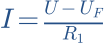
    I=\frac{U-U_F}{R_1}
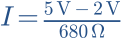
    I=\frac{5\,\mathrm{V}-2\,\mathrm{V}}{680\,\Omega}
    {I\approx4.41\,\mathrm{mA}}

    The LED usually becomes dimmer. Brightness is not exactly proportional to current.

Think it through before opening the answer. Always write the formula, substituted values and units.

Open the related article and interactive model →

Circuit 06 · 5 small steps

The diode as a current valve

Read circuits. Step by step. | LNGR SPKRAnode A_D is above, cathode K below. For hand calculation we assume a 0.7 V forward drop and zero reverse current. The real characteristic is gradual; the interactive diode model uses a different approximation.+−5 VAB · 0 VR1 = 1 kΩD1: U_F = 0.7 VMA_DK
Anode A_D is above, cathode K below. For hand calculation we assume a 0.7 V forward drop and zero reverse current. The real characteristic is gradual; the interactive diode model uses a different approximation.
  1. Is D1 forward or reverse biased?

    Hint

    The anode connects to the positive terminal through R1.

    Answer and working

    Forward biased. The cathode is the side with the bar in the symbol.

  2. Find the voltage across R1.

    Hint

    Subtract the assumed diode drop from 5 V.

    Answer and working
    Calculation notes
    U_R=U-U_F
    {U_R=5\,\mathrm{V}-0.7\,\mathrm{V}=4.3\,\mathrm{V}}
  3. Calculate current.

    Hint

    I = UR/R1.

    Answer and working
    Calculation notes
    I=\frac{U_R}{R_1}
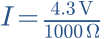
    I=\frac{4.3\,\mathrm{V}}{1000\,\Omega}
    {I=4.3\,\mathrm{mA}}
  4. Reverse D1 only. What happens in the model?

    Hint

    In reverse bias, the ideal diode interrupts the current path.

    Answer and working
    Calculation notes
    I=0
    U_R=R_1\cdot I=0\,\mathrm{V}
    {U_{AK}=-5\,\mathrm{V}}

    The negative sign refers to anode relative to cathode. Real diodes have leakage and a maximum reverse voltage.

  5. Why might the plot show a current other than 4.3 mA?

    Hint

    0.7 V is a calculation assumption, not a fixed law of nature.

    Answer and working

    The plot uses an exponential characteristic. UF depends on current, temperature and diode type. Compare the trend and state the model assumptions.

Think it through before opening the answer. Always write the formula, substituted values and units.

Open the related article and interactive model →

Circuit 07 · 5 small steps

Charging a capacitor

Read circuits. Step by step. | LNGR SPKRC1 is initially uncharged. At t = 0 the ideal source steps from 0 to 5 V. The drawn circuit then stays closed. C1 is ideal; M–B is its voltage.+−5 VAB · 0 VR1 = 1 kΩC1 = 1000 µFM
C1 is initially uncharged. At t = 0 the ideal source steps from 0 to 5 V. The drawn circuit then stays closed. C1 is ideal; M–B is its voltage.
  1. What is C1 voltage just after switching on?

    Hint

    Capacitor voltage cannot jump with finite current.

    Answer and working
    Calculation notes

    {u_C(0^+)=0\,\mathrm{V}}

    Capacitor voltage cannot jump with finite current.

  2. What is the initial current?

    Hint

    Initially the full 5 V appear across R1.

    Answer and working
    Calculation notes

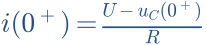
    i(0^+)=\frac{U-u_C(0^+)}{R}
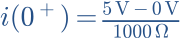
    i(0^+)=\frac{5\,\mathrm{V}-0\,\mathrm{V}}{1000\,\Omega}
    {i(0^+)=5\,\mathrm{mA}}
  3. Calculate the time constant τ.

    Hint

    1000 µF = 0.001 F; τ = R × C.

    Answer and working
    Calculation notes
    C=1000\,\mathrm{\mu F}=0.001\,\mathrm{F}
    \tau=R\cdot C
    \tau=1000\,\Omega\cdot0.001\,\mathrm{F}
    {\tau=1\,\mathrm{s}}
  4. Find UC and I after one time constant.

    Hint

    UC = U × (1 − e−t/τ); I = (U/R) × e−t/τ.

    Answer and working
    Calculation notes
    u_C(t)=U\left(1-e^{-\frac{t}{\tau}}\right)
    u_C(1\,\mathrm{s})=5\,\mathrm{V}\left(1-e^{-\frac{1\,\mathrm{s}}{1\,\mathrm{s}}}\right)
    {u_C(1\,\mathrm{s})\approx3.16\,\mathrm{V}}
    i(1\,\mathrm{s})=\frac{5\,\mathrm{V}}{1000\,\Omega}\cdot e^{-1}
    {i(1\,\mathrm{s})\approx1.84\,\mathrm{mA}}

    Check: resistor voltage plus capacitor voltage equals the source voltage.

  5. What happens after 5τ, and if R1 doubles?

    Hint

    After 5τ about 99.3% is reached.

    Answer and working
    Calculation notes
    u_C(5\tau)=5\,\mathrm{V}\left(1-e^{-5}\right)\approx4.966\,\mathrm{V}
    i(5\tau)=5\,\mathrm{mA}\cdot e^{-5}\approx0.0337\,\mathrm{mA}
    \tau_{\mathrm{new}}=2000\,\Omega\cdot0.001\,\mathrm{F}=2\,\mathrm{s}
    {i_{\mathrm{new}}(0^+)=\frac{5\,\mathrm{V}}{2000\,\Omega}=2.5\,\mathrm{mA}}

    The larger resistor slows charging. Final voltage stays the same.

Think it through before opening the answer. Always write the formula, substituted values and units.

Open the related article and interactive model →

Circuit 08 · 5 small steps

An inductor builds up current

Read circuits. Step by step. | LNGR SPKRAt t = 0 the source steps from 0 to 5 V. Initial current is zero. L1 is ideal with no winding resistance. R1 limits the eventual DC current.+−5 VAB · 0 VR1 = 100 ΩL1 = 100 mHM
At t = 0 the source steps from 0 to 5 V. Initial current is zero. L1 is ideal with no winding resistance. R1 limits the eventual DC current.
  1. What is I just after switching on?

    Hint

    Inductor current cannot jump with finite voltage.

    Answer and working
    Calculation notes
    {i_L(0^+)=0\,\mathrm{A}}
    u_R(0^+)=0\,\mathrm{V}
    u_L(0^+)=5\,\mathrm{V}

    Inductor current cannot jump with finite voltage.

  2. What current is reached eventually?

    Hint

    An ideal inductor has no voltage drop at steady DC.

    Answer and working
    Calculation notes
    I_{\infty}=\frac{U}{R}
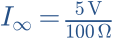
    I_{\infty}=\frac{5\,\mathrm{V}}{100\,\Omega}
    {I_{\infty}=0.05\,\mathrm{A}=50\,\mathrm{mA}}
  3. Calculate τ.

    Hint

    100 mH = 0.1 H; τ = L/R.

    Answer and working
    Calculation notes
    L=100\,\mathrm{mH}=0.1\,\mathrm{H}
    \tau=\frac{L}{R}
    \tau=\frac{0.1\,\mathrm{H}}{100\,\Omega}
    {\tau=0.001\,\mathrm{s}=1\,\mathrm{ms}}
  4. What is I at t = τ?

    Hint

    I = I∞ × (1 − e−t/τ).

    Answer and working
    Calculation notes
    i(t)=I_{\infty}\left(1-e^{-\frac{t}{\tau}}\right)
    i(1\,\mathrm{ms})=50\,\mathrm{mA}\left(1-e^{-1}\right)
    {i(1\,\mathrm{ms})\approx31.6\,\mathrm{mA}}
    u_R\approx100\,\Omega\cdot0.0316\,\mathrm{A}=3.16\,\mathrm{V}
    u_L\approx5\,\mathrm{V}-3.16\,\mathrm{V}=1.84\,\mathrm{V}
  5. Double L. What changes, and why is sudden disconnection different?

    Hint

    τ depends on L; I∞ does not.

    Answer and working
    Calculation notes

    \tau_{\mathrm{new}}=\frac{0.2\,\mathrm{H}}{100\,\Omega}=2\,\mathrm{ms}
    {I_{\infty}=\frac{5\,\mathrm{V}}{100\,\Omega}=50\,\mathrm{mA}}

    The larger inductor slows current rise. Sudden interruption can create high voltage; the turn-on model does not simulate this turn-off case.

Think it through before opening the answer. Always write the formula, substituted values and units.

Open the related article and interactive model →

Circuit 09 · 5 small steps

RC low-pass: measure across C

Read circuits. Step by step. | LNGR SPKRAn ideal sine source drives R1 and C1. Input A–B, output M–B. The output is unloaded. We compare peak amplitudes in steady state, not switch-on behaviour.~1 V peakAB · 0 VR1 = 1 kΩC1 = 100 nFM
An ideal sine source drives R1 and C1. Input A–B, output M–B. The output is unloaded. We compare peak amplitudes in steady state, not switch-on behaviour.
  1. Across which component is output measured?

    Hint

    Follow M and B.

    Answer and working

    Across C1. Choosing this output makes the arrangement a low-pass filter.

  2. What do you expect at very low frequency?

    Hint

    Capacitive reactance rises as frequency falls.

    Answer and working

    Almost the full input appears across C1: Uout approaches 1 V peak.

  3. Calculate cutoff frequency.

    Hint

    100 nF = 0.0000001 F; fc = 1/(2πRC).

    Answer and working
    Calculation notes

    C=100\,\mathrm{nF}=10^{-7}\,\mathrm{F}
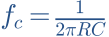
    f_c=\frac{1}{2\pi RC}
    f_c=\frac{1}{2\pi\cdot1000\,\Omega\cdot10^{-7}\,\mathrm{F}}
    {f_c\approx1592\,\mathrm{Hz}}
  4. What are output amplitude and phase at fc?

    Hint

    Magnitude is 1/√2; a low-pass has negative phase.

    Answer and working
    Calculation notes

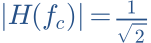
    |H(f_c)|=\frac{1}{\sqrt{2}}
    \hat U_{\mathrm{out}}=\frac{1\,\mathrm{V}}{\sqrt{2}}\approx0.707\,\mathrm{V}
    G=20\log_{10}\left(\frac{1}{\sqrt{2}}\right)\approx-3.01\,\mathrm{dB}
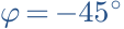
    {\varphi=-45^{\circ}}

    The voltage is not half of the input here.

  5. Double C1. Where does fc move? Check the filter model.

    Hint

    fc is inversely proportional to C.

    Answer and working
    Calculation notes

    C_{\mathrm{new}}=2C
    f_{c,\mathrm{new}}=\frac{1}{2\pi R\cdot2C}=\frac{f_c}{2}
    {f_{c,\mathrm{new}}\approx796\,\mathrm{Hz}}

    This calculation assumes no additional output load.

Think it through before opening the answer. Always write the formula, substituted values and units.

Open the related article and interactive model →

Circuit 10 · 5 small steps

RC high-pass: measure across R

Read circuits. Step by step. | LNGR SPKRC1 is now in the signal path; R1 connects M to B. Input A–B, output M–B. Ideal source, no additional load. Component values and cutoff match the low-pass example.~1 V peakAB · 0 VC1 = 100 nFR1 = 1 kΩM
C1 is now in the signal path; R1 connects M to B. Input A–B, output M–B. Ideal source, no additional load. Component values and cutoff match the low-pass example.
  1. Across which component is output measured?

    Hint

    Follow M and B.

    Answer and working

    Across R1. R and C have swapped positions compared with the low-pass.

  2. What output remains for a constant DC input?

    Hint

    After charging, no DC flows through the ideal capacitor.

    Answer and working
    Calculation notes

    I_{\mathrm{DC}}=0
    {U_{\mathrm{out,DC}}=R\cdot I_{\mathrm{DC}}=0\,\mathrm{V}}

    This applies at steady state. A transient output may appear at switch-on.

  3. Calculate fc.

    Hint

    fc = 1/(2πRC), regardless of which component is below.

    Answer and working
    Calculation notes

    f_c=\frac{1}{2\pi RC}
    f_c=\frac{1}{2\pi\cdot1000\,\Omega\cdot10^{-7}\,\mathrm{F}}
    {f_c\approx1592\,\mathrm{Hz}}

    The same cutoff does not mean the same response.

  4. Find amplitude and phase at fc.

    Hint

    Magnitude is 1/√2; high-pass output leads.

    Answer and working
    Calculation notes

    \hat U_{\mathrm{out}}=\frac{1\,\mathrm{V}}{\sqrt{2}}\approx0.707\,\mathrm{V}
    G\approx-3.01\,\mathrm{dB}
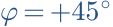
    {\varphi=+45^{\circ}}
  5. Compare high-pass and low-pass at 10 × fc.

    Hint

    High-pass: x/√(1+x²); low-pass: 1/√(1+x²), x=f/fc.

    Answer and working
    Calculation notes

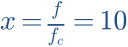
    x=\frac{f}{f_c}=10
    |H_{\mathrm{HP}}|=\frac{x}{\sqrt{1+x^2}}=\frac{10}{\sqrt{101}}
    {\hat U_{\mathrm{HP}}\approx0.995\,\mathrm{V}}
    |H_{\mathrm{LP}}|=\frac{1}{\sqrt{1+x^2}}=\frac{1}{\sqrt{101}}
    {\hat U_{\mathrm{LP}}\approx0.0995\,\mathrm{V}}

    Compare both model curves near 15.9 kHz.

Think it through before opening the answer. Always write the formula, substituted values and units.

Open the related article and interactive model →