
Dividing voltage — with a load
What is the resistance between A and B?
Hint
Add R1 and R2.
Answer and working
Calculation notes

What current flows through the unloaded divider?
Hint
I = 5 V / 10,000 Ω.
Answer and working
Calculation notes
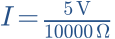

What is the output voltage between M and B?
Hint
UMB = I × R2.
Answer and working
Calculation notes


Now connect RL = 10 kΩ between M and B. Find R2 parallel RL.
Hint
Rparallel = R2 × RL / (R2 + RL).
Answer and working
Calculation notes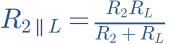


The dashed load is parallel to the lower resistor.
Calculate the loaded output voltage and check the potentiometer model.
Hint
Uout = 5 V × Rlower / (R1 + Rlower).
Answer and working
Calculation notes


The load reduces output voltage. Check the model: 10 kΩ, midpoint, 10 kΩ load.
Think it through before opening the answer. Always write the formula, substituted values and units.
The mental picture
Think of a movable tap on a resistive track. The wiper divides it into an upper and a lower section. Moving it changes their ratio. Resistance between the two outer terminals ideally stays constant.
The principle
An unloaded linear potentiometer produces voltage proportional to position. A load between wiper and ground sits in parallel with the lower section and changes the division. A logarithmic volume pot deliberately has another curve. This tool models a linear pot.
Try it yourself
The potentiometer
Set the wiper to 50% and compare a 100 kΩ load with 1 kΩ. The knob stays still, but output voltage falls as loading increases.
Model limits: Linear resistive track, ideal 5 V source and resistive load. No contact noise or intermittent wiper contact.
A worked example
A 10 kΩ pot across 5 V gives 2.5 V at its unloaded midpoint. A 10 kΩ load across the lower 5 kΩ section reduces this to 2 V. The circuit connected to the wiper belongs in the calculation.
A closer look · equations and assumptions


The Thevenin equivalent is the unloaded divider voltage in series with R1 ∥ R2. A potentiometer’s source resistance is highest at the midpoint. A high-input-impedance buffer can reduce loading, but its input characteristics still require checking.
A common pitfall. An ordinary signal potentiometer is not a loudspeaker power attenuator. A speaker L-pad requires appropriate power ratings and a different resistor arrangement.
Workshop takeaway
The third terminal is no mystery: two ends and one wiper. Then check what the wiper is connected to.
Sources & transparency
Original illustrations and educational calculations. No measurements of a specific product. Edited 11 October 2026.
Work it out · answers unfold
Write down your prediction first, then your calculation. Open the answer only when you are ready to compare.
14 · Divider: R1 = 2 kΩ upper, R2 = 3 kΩ lower, input 10 V. Unloaded output across R2. Find output.
Show worked answer
- Total resistance: 5 kΩ.
- Current: 2 mA.
- Voltage across R2: 6 V.

15 · Load the divider in task 14 with 3 kΩ across R2. Find the new output.
Show worked answer
- R2 parallel load = 1.5 kΩ.
- Total resistance: 3.5 kΩ.
- Output = 10 · 1.5/3.5 = 4.286 V.

16 · An unloaded divider should turn 12 V into 3 V. Choose R2 = 1 kΩ. Find R1.
Show worked answer
- Output is one quarter of input.
- Total resistance must be four times R2.
- R1 = 4 kΩ - 1 kΩ = 3 kΩ.

18 · A 1 kΩ resistor has ±5% tolerance. Find minimum and maximum current at ideal 5 V.
Show worked answer
- Rmin = 950 Ω, Rmax = 1050 Ω.
- Minimum I uses maximum R: 4.762 mA.
- Maximum I uses minimum R: 5.263 mA.
