
Charging a capacitor
What is C1 voltage just after switching on?
Hint
Capacitor voltage cannot jump with finite current.
Answer and working
Calculation notes
Capacitor voltage cannot jump with finite current.
What is the initial current?
Hint
Initially the full 5 V appear across R1.
Answer and working
Calculation notes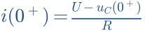
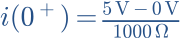

Calculate the time constant τ.
Hint
1000 µF = 0.001 F; τ = R × C.
Answer and working
Calculation notes



Find UC and I after one time constant.
Hint
UC = U × (1 − e−t/τ); I = (U/R) × e−t/τ.
Answer and working
Calculation notes




Check: resistor voltage plus capacitor voltage equals the source voltage.
What happens after 5τ, and if R1 doubles?
Hint
After 5τ about 99.3% is reached.
Answer and working
Calculation notes



The larger resistor slows charging. Final voltage stays the same.
Think it through before opening the answer. Always write the formula, substituted values and units.
Store energy. Give it back.
Imagine an elastic membrane inside a closed water pipe. Apply pressure on one side and it bends. Water on the other side moves, even though none passes through the membrane.
This is a useful picture for a capacitor: two conducting surfaces are separated by an insulator. A voltage source moves charge through the external wires. Equal and opposite charges build up on the electrodes. An electric field forms between them and stores energy.
What does “high capacitance” mean?
Capacitance C tells you how much charge is stored per volt. At the same voltage, a higher-capacitance component carries more charge on its electrodes. The unit is the farad, F. Electronics commonly uses µF, nF and pF: microfarads, nanofarads and picofarads.


For example, 100 µF at 5 V gives 500 µC of charge on the positive electrode and −500 µC on the negative one. Capacitance is neither a time nor a power rating.
A closer look · Area, spacing and energy
For an ideal parallel-plate capacitor, C = ε₀ · εᵣ · A / d. More electrode area A and a smaller separation d increase capacitance. εᵣ describes the insulating material. This approximation neglects edge fields.
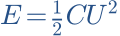


Doubling voltage at the same capacitance means four times the stored energy. This does not permit exceeding the rated voltage.
Three forms. One underlying idea.
The shape suggests a component family, but it does not reliably tell you the value. Read the markings and the datasheet. These drawings show typical forms, not products to scale.
Film capacitor
Insulating plastic film between electrodes. Common in passive speaker crossovers; normally non-polarised.
Audio · FiltersAluminium electrolytic
High capacitance in a small package. Usually polarised: on this typical style, the stripe marks the negative terminal. Bipolar types are marked separately.
Power · Bulk storageCeramic capacitor
Often tiny, with no readable markings. Common beside IC power pins. Properties depend strongly on the ceramic type.
Microcontrollers · DecouplingRead the example markings
| Marking | Meaning |
|---|---|
| 4.7 µF | Nominal capacitance. Components often use a decimal point. |
| ±5 % | Capacitance tolerance: here 4.465 to 4.935 µF under the specified test conditions. |
| 250 V DC | DC voltage rating under datasheet conditions. Not equivalent to a 250 V AC rating. |
The application decides. An ordinary polarised electrolytic is not a direct replacement for a non-polarised crossover capacitor. AC without appropriate DC bias requires a suitable component type.
Why charging takes time.
A source charges the capacitor through a resistor. Initially the capacitor voltage is zero. The full source voltage is across the resistor, so current is greatest. As capacitor voltage rises, less voltage remains across the resistor and current decreases.
Think of tensioning a spring: as you progress, the opposing force grows. The resistor limits current. A finite current cannot change an ideal capacitor’s voltage instantaneously.
Change a value. See the effect.
Try this: Double the resistance. Watch the initial current and time constant. Then double only capacitance: what stays the same about initial current?
The time axis automatically spans 5τ. Compare the seconds and current values, not just the curve shape. Discharge current is negative because it flows opposite to the indicated charging direction.
Model: ideal capacitor, resistor and voltage source; no leakage current. Each mode starts a fresh scenario; switching modes does not continue an ongoing simulation.
The time constant τ = R · C links resistance and capacitance. After one time constant, charging reaches about 63.2% of the final voltage. Discharging leaves about 36.8%. After 5τ the model is about 99.3% charged or has 0.67% remaining, rather than reaching the limit exactly.
A closer look · From the loop equation to the exponential
The series voltages add up to U₀. Using uR = R · i and i = C · duC/dt gives:
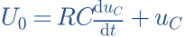


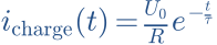


With 1 kΩ and 100 µF, τ = 1 000 Ω · 0.0001 F = 0.1 s. At 5 V, initial current is 5 mA; after 0.1 s it is about 1.84 mA. Capacitor voltage is then about 3.16 V.
When charging from zero to U₀ through a resistor from a constant ideal voltage source, half the supplied energy is stored in the capacitor and half is dissipated in the resistor. This balance applies to this particular charging scenario.
What if the voltage keeps changing?
A sinusoidal voltage repeatedly changes the capacitor’s charge. The faster its voltage changes, the more current is needed at the same capacitance. Frequency f counts cycles per second; its unit is hertz, Hz.
Capacitive reactance describes the ratio of voltage amplitude to current amplitude. Its magnitude |XC| falls as frequency rises. An ideal capacitor takes in energy and returns it; its average real power dissipation is zero.
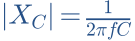
Higher frequency. Lower reactance.
Try this: Increase frequency by a factor of ten. Watch |XC| and current while keeping voltage constant.
The lower plot always shows two cycles. Each curve is normalised to its own peak: equal heights do not mean equal numerical values or units. Actual RMS current is shown above.
Model: ideal capacitor directly across an ideal sine-voltage source; no series resistance, ESR or current limit. High calculated currents are not construction recommendations.
Why current gets there first
At a zero crossing, the sine voltage changes fastest, so current magnitude is greatest. At a positive or negative voltage peak, its slope is momentarily zero, so current is zero. Current therefore leads voltage across an ideal capacitor by a quarter-cycle, or 90°.
A closer look · Derivative, RMS and complex impedance



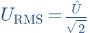
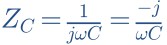
j is the imaginary unit, with j² = −1. Here it represents a phase rotation. An ideal capacitor’s impedance has a phase of −90°, because impedance is voltage divided by current. This agrees with current leading voltage by +90°.
The peak-to-RMS relationship above applies to a sine wave. Other waveforms require the RMS value to be determined from their time dependence.
A capacitor becomes a high-pass filter.
Now add a resistor after the capacitor and measure output voltage across it. At low frequencies, |XC| is large and much of the input voltage appears across the capacitor. At high frequencies, |XC| is small and almost all the input voltage appears across the resistor.
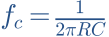
This creates a frequency-dependent voltage divider. The corner frequency fc is where output voltage falls to about 70.7% of its passband value: −3.01 dB. It is not a sharp boundary below which everything disappears.
What changes with 4.7 instead of 10 µF?
Try this: Keep R at 8 Ω. Compare 4.7 µF with 10 µF. Which value produces more voltage across the load at 1 kHz?
Model: ideal capacitor, ideal source with zero output resistance and a purely resistive load. The plot shows an electrical voltage ratio, not a sound-pressure response.
A tweeter is not an 8 Ω resistor. Its impedance varies with frequency, and its own acoustic response and the baffle also matter. This calculator explains the principle; a reliable speaker crossover needs suitable driver data, simulation and measurement.
A closer look · Transfer function, slope and phase

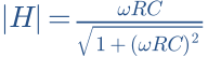


At fc, magnitude and phase are −3.01 dB and +45°. Well below fc, magnitude rises at about 6 dB per octave or 20 dB per decade. Well above it, magnitude approaches 0 dB and phase approaches 0°.
For 4.7 µF into 8 Ω: fc = 1 / (2π · 8 Ω · 4.7 · 10⁻⁶ F) ≈ 4 233 Hz. With 10 µF it is about 1 989 Hz. Higher capacitance lowers the corner frequency here.
For complex speaker impedance ZL(f), H(f) = ZL(f) / [ZC(f) + ZL(f)] for an ideal source. The overall acoustic response also requires the driver’s complex acoustic transfer function.
Ideal on paper.
Real on the workbench.
So far the models have isolated the basic principle. A real component has additional properties. They matter when choosing parts, laying out a PCB or comparing calculations with measurements.
| Property | Practical consequence |
|---|---|
| ESR | Equivalent series resistance causes losses and heating. With an appropriate ESR value, power loss is approximately I_RMS² · ESR. |
| ESL | Leads and construction add inductance. Above self-resonance, the component can behave predominantly inductively. |
| Leakage | Insulation is imperfect. A charged real capacitor does not retain its voltage indefinitely. |
| Tolerance & operating conditions | Actual capacitance can differ from its marking. Temperature, frequency and, for some ceramics, DC bias affect the effective value. |
A closer look · A simple equivalent circuit


This is a simplified series model. Leakage can additionally be represented by a large parallel resistance. Real ESR also depends on frequency, so one number cannot describe all behaviour. Manufacturer curves are more useful than a blanket “better”.
Side trip: power supply
A reservoir capacitor can deliver charge during a short supply interruption. For approximately constant load current, ΔU ≈ I · Δt / C. Example: 10 mA for 1 ms produces an idealised 0.1 V drop across 100 µF. ESR and the rest of the supply add further effects.
Side trip: microcontroller
Switching causes short current transients. A correctly placed decoupling capacitor supports the supply locally. Capacitance alone is not enough: short current paths and low loop inductance matter. Choose values and placement from the specific controller’s documentation.
For a first physical experiment: Use a current-limited low-voltage supply, such as 5 V, and a charging resistor. Observe polarity and voltage rating. Before rewiring, discharge through a suitable resistor and check the remaining voltage. An opened mains power supply is not a beginner experiment.
Start with the job.
Then choose the capacitor.
More microfarads is not automatically better. In a high-pass, a larger value lets more low-frequency content through. As a reservoir, it can reduce voltage drop. Charging it means moving more charge. The same change in value has different practical consequences in different circuits.
On the bench: understand the circuit, calculate the value, check the type and datasheet, then measure. An expensive capacitor does not fix a poor alignment. A neat calculator curve is only the beginning of a good crossover.
Sources & model basis
The tools calculate the idealised equations stated on this page. They do not use measurements of specific components. Further technical reading is available in these open educational and manufacturer resources:
- MIT OpenCourseWare · Capacitance & stored energy ↗
- Murata · Impedance, ESR & frequency characteristics ↗
- TDK · Film capacitors: general technical information (PDF) ↗
- Texas Instruments · Decoupling capacitors & layout ↗
All component and functional illustrations were created for this page. No manufacturer photos were copied. Technical revision: 11 October 2026. Sample page v0.1 for editorial review.
Work it out · answers unfold
Write down your prediction first, then your calculation. Open the answer only when you are ready to compare.
01 · A 100 µF capacitor is at 5 V. Calculate stored charge.
Show worked answer
- Convert capacitance: 0.0001 F.
- Q = C · U.
- Q = 0.0005 C = 0.5 mC.

02 · How much energy does the same capacitor store at 5 V?
Show worked answer
- Square voltage: 25 V².
- Multiply by C and halve.
- E = 1.25 mJ.

03 · An uncharged 100 µF capacitor charges through 10 kΩ from 5 V. Find τ and initial current.
Show worked answer
- Time constant: R · C = 1 s.
- At t = 0 the capacitor is still at 0 V.
- Initial I = 5/10000 = 0.5 mA.

04 · Calculate capacitor voltage after one time constant in task 3.
Show worked answer
- t/τ = 1.
- Charging factor: 1 - exp(-1) = 0.6321.
- Capacitor voltage = 3.161 V.
