
An inductor builds up current
What is I just after switching on?
Hint
Inductor current cannot jump with finite voltage.
Answer and working
Calculation notes


Inductor current cannot jump with finite voltage.
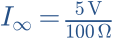
What current is reached eventually?
Hint
An ideal inductor has no voltage drop at steady DC.
Answer and working
Calculation notes

Calculate τ.
Hint
100 mH = 0.1 H; τ = L/R.
Answer and working
Calculation notes



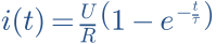
What is I at t = τ?
Hint
I = I∞ × (1 − e−t/τ).
Answer and working
Calculation notes




Double L. What changes, and why is sudden disconnection different?
Hint
τ depends on L; I∞ does not.
Answer and working
Calculation notes

The larger inductor slows current rise. Sudden interruption can create high voltage; the turn-on model does not simulate this turn-off case.
Think it through before opening the answer. Always write the formula, substituted values and units.
The mental picture
A heavy flywheel cannot speed up or stop instantly. An inductor similarly reacts to changes in current. Its energy is stored in a magnetic field rather than a rotating mass. The analogy explains inertia, not all the electromagnetic physics.
The principle
Wire turns concentrate the magnetic effect of current. Inductance L is measured in henries; speaker crossovers often use millihenries. The wire also has DC resistance. Air-core and magnetic-core inductors differ in size, losses and possible core saturation.
Try it yourself
The inductor
Double L at fixed R and U. Final current stays unchanged, but the rise takes longer. Then increase R and watch both final current and time constant.
Model limits: Linear ideal inductor plus the selected series resistance; no core saturation. Time axis automatically spans 0 to 5τ.
A worked example
10 mH with 10 Ω gives τ = 1 ms. At 5 V, current approaches 0.5 A. After 1 ms it reaches about 0.316 A. At 1 kHz, the ideal inductor has a reactance of about 62.8 Ω.
A closer look · equations and assumptions
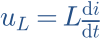

For sinusoidal current, voltage across an ideal L leads current by 90°. A magnetic core can saturate at high current, reducing effective inductance. A real coil also has parasitic capacitance, so XL = 2πfL does not remain valid to arbitrarily high frequencies.
A common pitfall. Abruptly interrupting inductor current can produce a high voltage. A transistor driving an inductive load needs suitable clamping, such as a flyback diode for a DC relay.
Workshop takeaway
Compare more than millihenries: include winding resistance, current and mounting. Adjacent crossover coils can couple magnetically.
Sources & transparency
Original illustrations and educational calculations. No measurements of a specific product. Edited 11 October 2026.
Work it out · answers unfold
Write down your prediction first, then your calculation. Open the answer only when you are ready to compare.
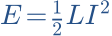
17 · An ideal 10 mH inductor carries 0.2 A. Calculate stored magnetic energy.
Show worked answer
- L = 0.01 H.
- Square current and multiply by L/2.
- E = 0.2 mJ.

18 · 10 mH and 100 Ω are in series across 5 V. Find τ and steady current; ideal inductor.
Show worked answer
- τ = L/R = 0.1 ms.
- The ideal inductor has zero steady DC voltage.
- Final I = 5/100 = 50 mA.

19 · Calculate inductor current in task 18 after 0.1 ms, starting at zero.
Show worked answer
- Time equals τ.
- Current rises to 63.21% of final value.
- I = 31.61 mA.

20 · A 10 mH inductor changes current by 0.2 A in 10 µs. What ideal voltage magnitude is needed? What does this imply at turn-off?
Show worked answer
- Slope: ΔI/Δt = 20000 A/s.
- U = L · ΔI/Δt = 200 V.
- A limiting current path, such as a suitable flyback diode, prevents uncontrolled spikes.
