
The diode as a current valve
Is D1 forward or reverse biased?
Hint
The anode connects to the positive terminal through R1.
Answer and working
Forward biased. The cathode is the side with the bar in the symbol.
Find the voltage across R1.
Hint
Subtract the assumed diode drop from 5 V.
Answer and working
Calculation notes

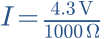
Calculate current.
Hint
I = UR/R1.
Answer and working
Calculation notes

Reverse D1 only. What happens in the model?
Hint
In reverse bias, the ideal diode interrupts the current path.
Answer and working
Calculation notes


The negative sign refers to anode relative to cathode. Real diodes have leakage and a maximum reverse voltage.
Why might the plot show a current other than 4.3 mA?
Hint
0.7 V is a calculation assumption, not a fixed law of nature.
Answer and working
The plot uses an exponential characteristic. UF depends on current, temperature and diode type. Compare the trend and state the model assumptions.
Think it through before opening the answer. Always write the formula, substituted values and units.
The mental picture
A check valve is a useful starting point: it opens forward and restricts reverse flow. A diode has no single magic opening voltage. Current rises steeply with forward voltage, and temperature and component type change the relationship.
The principle
The terminals are anode and cathode. On a typical rectifier diode, the body stripe usually marks the cathode. In forward conduction the anode is more positive. Maximum reverse voltage and current are specified in the datasheet.
Try it yourself
The diode
Move the source from negative to positive voltage. Watch the series resistor limit current. Then reduce it: current rises, but the forward voltage is not simply constant.
Model limits: Illustrative exponential characteristic with series resistance. No specific semiconductor or breakdown simulation.
A worked example
For rectification, a diode can pass part of an AC waveform. A bridge uses four diodes, with two conducting in each current path. A capacitor after the bridge can support the voltage between peaks.
A closer look · equations and assumptions


The tool solves the diode and resistor together. IS = 1 nA and n·UT = 52 mV are illustrative parameters, not product data. Reverse operation uses a small constant leakage current. Breakdown, reverse recovery, capacitance and self-heating are omitted; those effects can dominate fast switching circuits.
A common pitfall. “A diode always drops 0.7 V” is only a rough shortcut. Schottky, silicon and light-emitting diodes have different curves, and operating current matters.
Workshop takeaway
Check the stripe, current direction and datasheet first. Do not omit current limiting on a guess.
Sources & transparency
Original illustrations and educational calculations. No measurements of a specific product. Edited 11 October 2026.
Work it out · answers unfold
Write down your prediction first, then your calculation. Open the answer only when you are ready to compare.
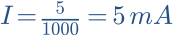
01 · An ideal diode is in series with 1 kΩ across 5 V, anode towards positive. Find current.
Show worked answer
- The diode conducts with zero drop in this model.
- The resistor receives all 5 V.
- I = 5 mA.
02 · Reverse the ideal diode in task 1. What are current and resistor voltage?
Show worked answer
- Diode blocks.
- I = 0 A.
- Resistor voltage = 0 V; diode takes source voltage.
03 · Repeat task 1 with a constant diode drop of 0.7 V.
Show worked answer
- Resistor voltage: 5 - 0.7 = 4.3 V.
- I = UR/R.
- I = 4.3 mA.

07 · Why is 0.7 V not a universal hard diode turn-on threshold?
Show worked answer
- Current changes continuously with voltage.
- Temperature and diode type affect the curve.
- 0.7 V is a simplified calculation assumption.