
Two resistors in series
Are there one or two paths from A to B?
Hint
Look for a branch.
Answer and working
There is exactly one path. Both resistors carry the same current.
Calculate the total resistance.
Hint
Series resistances add.
Answer and working
Calculation notes


Find the current through R1 and R2.
Hint
Use the full source voltage and total resistance.
Answer and working
Calculation notes
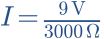

Find UAM and UMB.
Hint
For each resistor, U = R × I.
Answer and working
Calculation notes



What do red at M and black at B read? What if R1 and R2 swap places?
Hint
You measure across the lower resistor only.
Answer and working
Calculation notes



After swapping, the smaller resistor is below. Total current stays the same.
Think it through before opening the answer. Always write the formula, substituted values and units.
Two parallel current paths
What is the voltage across each resistor?
Hint
Their terminals connect to the same two nodes.
Answer and working
Calculation notes
Voltage does not split here.
Calculate current in the first branch.
Hint
I1 = U/R1.
Answer and working
Calculation notes
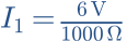

Calculate current in the second branch.
Hint
I2 = U/R2.
Answer and working
Calculation notes
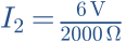

How much current must the source supply?
Hint
Branch currents add at the node.
Answer and working
Calculation notes



R2 is disconnected. Does current in R1 increase?
Hint
The ideal source still maintains 6 V.
Answer and working
Calculation notes


Current in the first branch stays the same. Only total current falls.
Think it through before opening the answer. Always write the formula, substituted values and units.
The mental picture
In one path, charge must pass through both resistors in turn. With two parallel paths, current splits. A drawing may look tangled: electrical nodes matter, not placement on the page.
The principle
Series resistors carry the same current, and their voltage drops add. Parallel resistors have the same voltage across them, and their branch currents add. These rules also help check loudspeaker wiring.
Try it yourself
Series & parallel
Start with equal resistors and compare total resistance and source current. Increase only R2: which connection behaves differently from what you first expected?
Model limits: Two ideal ohmic resistors. No speaker resonances or cable losses.
A worked example
Two 100 Ω resistors give 200 Ω in series and 50 Ω in parallel. At 5 V, total currents are 25 mA and 100 mA respectively. Each parallel branch carries 50 mA.
A closer look · equations and assumptions



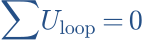
Kirchhoff’s laws generalise these relationships to networks. AC analysis can use complex impedances under suitable steady-state linear conditions. A speaker’s nominal impedance is not a substitute for its frequency-dependent impedance curve.
A common pitfall. Two nominal 4 Ω speakers in parallel give nominally 2 Ω. The amplifier’s ability to drive the actual load must be checked separately.
Workshop takeaway
Trace the nodes and write down the expected resistance before powering up. Then measure whether the wiring matches.
Sources & transparency
Original illustrations and educational calculations. No measurements of a specific product. Edited 11 October 2026.
Work it out · answers unfold
Write down your prediction first, then your calculation. Open the answer only when you are ready to compare.
07 · 300 Ω and 600 Ω are parallel across 6 V. Find branch and total currents.
Show worked answer
- I1 = 20 mA; I2 = 10 mA.
- Currents add at the node.
- Total current: 30 mA.

08 · Without calculating: can 300 Ω in parallel with 600 Ω exceed 300 Ω? Explain.
Show worked answer
- No.
- The extra branch allows more current at the same voltage.
- Equivalent resistance is below the smallest branch resistance.
09 · Mixed: R1 = 100 Ω in series with R2 = 300 Ω parallel R3 = 600 Ω; source 12 V. Find total R.
Show worked answer
- First replace the parallel group: 200 Ω.
- Then add R1.
- Total R = 300 Ω.

10 · Use the mixed circuit in task 9. Find total current and parallel-group voltage.
Show worked answer
- Total I = 12/300 = 40 mA.
- U1 = 0.04 · 100 = 4 V.
- R2 and R3 each have 8 V across them.
