
The mental picture
A controller compares target and actual values, correcting until the difference is small. A feedback op amp compares part of its output with its input. This works only while the amplifier is fast enough and its output can reach the required value.
The principle
The inputs are non-inverting (+) and inverting (−); they are not power-supply pins. In a non-inverting amplifier, a feedback resistor divider sets gain. Supply range, input common-mode range and output swing remain component-dependent.
Try it yourself
The operational amplifier
Increase gain until the output becomes flat at its top and bottom. Then reduce input amplitude. Clipping depends on signal, gain and available headroom together.
Model limits: Ideal amplifier with hard clipping 1 V inside each supply rail. Required slew rate is calculated but slew distortion is not simulated.
A worked example
A gain of 5 turns a 0.5 V input peak into an ideal 2.5 V output peak. With ±5 V supplies and an assumed 1 V margin to each rail, this model clips at ±4 V.
A closer look · equations and assumptions
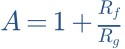


For a dominant-pole op amp, small-signal bandwidth is approximately GBW/A when that model and stability conditions apply. Slew rate additionally limits voltage change per unit time. An op amp can therefore distort large high-frequency signals despite adequate supply voltage.
A common pitfall. “Rail-to-rail” does not mean exactly reaching both rails under every load. Input and output specifications are separate.
Workshop takeaway
Write down gain, maximum signal amplitude, supply and load before choosing an op amp. Then consider the finer noise and distortion specifications.
Sources & transparency
- MIT OpenCourseWare · Circuits and Electronics ↗
- Texas Instruments · Operational amplifier specifications ↗
Original illustrations and educational calculations. No measurements of a specific product. Edited 11 October 2026.
Work it out · answers unfold
Write down your prediction first, then your calculation. Open the answer only when you are ready to compare.
14 · Divider: R1 = 2 kΩ upper, R2 = 3 kΩ lower, input 10 V. Unloaded output across R2. Find output.
Show worked answer
- Total resistance: 5 kΩ.
- Current: 2 mA.
- Voltage across R2: 6 V.

15 · Load the divider in task 14 with 3 kΩ across R2. Find the new output.
Show worked answer
- R2 parallel load = 1.5 kΩ.
- Total resistance: 3.5 kΩ.
- Output = 10 · 1.5/3.5 = 4.286 V.

16 · An unloaded divider should turn 12 V into 3 V. Choose R2 = 1 kΩ. Find R1.
Show worked answer
- Output is one quarter of input.
- Total resistance must be four times R2.
- R1 = 4 kΩ - 1 kΩ = 3 kΩ.

19 · How do you connect ideal ammeter and voltmeter to a resistor? Explain the short-circuit mistake.
Show worked answer
- Ammeter in series with the current path.
- Voltmeter in parallel across the resistor.
- An ammeter across the source nearly shorts it.