
Decoupling: a local reserve in the right place
Step by step: understand, predict, adjust and calculate.
01 · Why supply voltage briefly dips
A microcontroller can change its current demand quickly. Power reaches it through wires and traces with resistance and inductance. A distant regulator cannot instantly compensate every current step right at the chip. A local capacitor provides charge during that brief interval.
02 · Decoupling is not galvanic isolation
Supply decoupling aims to keep local current changes from disturbing other sections. The common return usually remains connected. A signal coupling capacitor has a different job: it blocks DC and passes changing signals, forming a high-pass with the following resistance. Galvanic isolation instead requires an appropriate isolation mechanism such as a transformer or isolator.
03 · Estimate the required charge first
Assume an extra 20 mA for 1 ms. If the source supplies no additional current during that pulse, 20 µC of charge is missing. An ideal 100 µF capacitor loses 0.2 V. This deliberately simple estimate describes neither regulator dynamics nor arbitrary pulse shapes.
04 · ESR adds an immediate step
In addition to the falling voltage caused by discharge, ESR adds a voltage drop. At 20 mA and 0.1 Ω that is 2 mV. Very fast events also depend on ESL and the entire current loop. More capacitance alone therefore does not solve every problem. Short forward and return paths and IC/regulator guidance matter too.
05 · Do not confuse charge and energy
At fixed capacitance, capacitor voltage follows relative charge. Energy, however, rises with the square of voltage. At half voltage the capacitor stores only a quarter of full energy. The second animation shows separate bars and lets you pause the process.
Workshop takeaway
The capacitor must deliver current where it is needed. Start with the pulse, acceptable droop and current loop, then choose the value.
Work it out · answers unfold
Write down your prediction first, then your calculation. Open the answer only when you are ready to compare.
01 · A 100 µF capacitor is at 5 V. Calculate stored charge.
Show worked answer
- Convert capacitance: 0.0001 F.
- Q = C · U.
- Q = 0.0005 C = 0.5 mC.

02 · How much energy does the same capacitor store at 5 V?
Show worked answer
- Square voltage: 25 V².
- Multiply by C and halve.
- E = 1.25 mJ.

03 · An uncharged 100 µF capacitor charges through 10 kΩ from 5 V. Find τ and initial current.
Show worked answer
- Time constant: R · C = 1 s.
- At t = 0 the capacitor is still at 0 V.
- Initial I = 5/10000 = 0.5 mA.

04 · Calculate capacitor voltage after one time constant in task 3.
Show worked answer
- t/τ = 1.
- Charging factor: 1 - exp(-1) = 0.6321.
- Capacitor voltage = 3.161 V.

05 · Calculate charging current after one time constant in task 3.
Show worked answer
- Voltage across R is 5 - 3.161 = 1.839 V.
- Divide by 10 kΩ.
- I = 0.1839 mA.

06 · How long does task 3 take to charge to 90% of final voltage?
Show worked answer
- Remaining fraction is 0.1.
- Use logarithm: t = -τ ln(0.1).
- t = 2.303 s.

07 · 100 µF discharges from 5 V through 10 kΩ. Calculate voltage after 2 s.
Show worked answer
- τ = 1 s.
- Use discharge formula.
- Voltage = 5 · exp(-2) = 0.677 V.

08 · Does this ideal discharge stop at 0.7 V? Explain without calculation.
Show worked answer
- No, the RC circuit has no such threshold.
- Voltage and current approach zero.
- A diode path would require a different circuit model.
09 · How long does discharge in task 7 take to fall below 0.1 V?
Show worked answer
- Ratio: 0.1/5 = 0.02.
- t = τ ln(5/0.1).
- At 3.912 s it is 0.1 V; thereafter below.

10 · An ideal 10 µF capacitor carries sinusoidal current at 100 Hz. Find reactance magnitude.
Show worked answer
- C = 10 · 10⁻⁶ F.
- Form 2πfC and take its reciprocal.
- Reactance magnitude = 159.15 Ω.

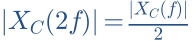
11 · Double the frequency in task 10. How do reactance and current change at fixed voltage?
Show worked answer
- Reactance halves to 79.58 Ω.
- I = U/XC.
- Current magnitude doubles.
12 · An IC needs an extra 20 mA for 10 µs. What ideal capacitance limits voltage droop to 0.1 V?
Show worked answer
- Extra charge: I · Δt = 0.2 µC.
- C = ΔQ/ΔU.
- At least 2 µF in the ideal model.

13 · A decoupling capacitor has 0.1 Ω ESR. A current step is 0.5 A. Find the immediate ESR voltage step.
Show worked answer
- Apply Ohm’s law to ESR.
- ΔU = ΔI · ESR.
- ΔU = 50 mV; further capacitive droop follows.

14 · Why place a small decoupling capacitor next to the IC rather than 30 cm away?
Show worked answer
- Wires have inductance.
- Fast current changes create voltage drops across it.
- Short supply and return paths reduce loop area.
15 · A 1 µF coupling capacitor feeds an ideal 10 kΩ input. Ideal source. Find high-pass cutoff.
Show worked answer
- R and C form a high-pass.
- RC = 0.01 s.
- Cutoff = 15.92 Hz.

16 · Distinguish signal coupling from supply decoupling by the current path.
Show worked answer
- Coupling: capacitor in series with signal, blocks steady DC.
- Decoupling: capacitor across supply, supports local current peaks.
- Same component type, different purpose.
17 · An ideal 10 mH inductor carries 0.2 A. Calculate stored magnetic energy.
Show worked answer
- L = 0.01 H.
- Square current and multiply by L/2.
- E = 0.2 mJ.

18 · 10 mH and 100 Ω are in series across 5 V. Find τ and steady current; ideal inductor.
Show worked answer
- τ = L/R = 0.1 ms.
- The ideal inductor has zero steady DC voltage.
- Final I = 5/100 = 50 mA.

19 · Calculate inductor current in task 18 after 0.1 ms, starting at zero.
Show worked answer
- Time equals τ.
- Current rises to 63.21% of final value.
- I = 31.61 mA.

20 · A 10 mH inductor changes current by 0.2 A in 10 µs. What ideal voltage magnitude is needed? What does this imply at turn-off?
Show worked answer
- Slope: ΔI/Δt = 20000 A/s.
- U = L · ΔI/Δt = 200 V.
- A limiting current path, such as a suitable flyback diode, prevents uncontrolled spikes.

Further reading
Original teaching models and authored exercises. Sources provide technical background; no manufacturer measurement curves are reproduced.