
Switch with a small signal
Step by step: understand, predict, adjust and calculate.
01 · Two paths, one reference
A microcontroller should switch a load. Its output provides the control signal while the supply provides load energy. In the NPN low-side switch shown, the emitter connects to the common return. When the transistor turns on, its collector connects the load to that return.
02 · The base resistor has a job
The base-emitter junction behaves approximately like a diode. Its resistor limits current. For the first calculation we subtract 0.7 V from the control voltage. This is a model assumption, not a fixed switching threshold for every transistor and temperature.
03 · Saturation limits the result
Initially more base current may allow more collector current. Eventually the supply and load limit it. More base current then does not mean unlimited load current. The animation uses a conservative forced gain of 20 and an assumed saturation voltage of 0.2 V. Check real datasheet values and GPIO limits before building.
04 · Why a MOSFET is driven differently
An ideal MOSFET gate needs no continuous static control current. Switching still requires charging and discharging its capacitance. Threshold voltage does not tell you when the device is sufficiently conductive for your load. Look for a guaranteed on-resistance at the available gate voltage.
05 · Inductive loads need a turn-off path
The drawing uses a resistive load. A relay or motor behaves differently at turn-off: stored magnetic energy needs a path. An appropriately rated flyback or clamp circuit therefore belongs in the design. This resistive-load animation does not simulate that turn-off spike.
Workshop takeaway
Calculate control current, load current and dissipation separately. “It switches somehow” is not a finished design.
Work it out · answers unfold
Write down your prediction first, then your calculation. Open the answer only when you are ready to compare.
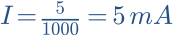
01 · An ideal diode is in series with 1 kΩ across 5 V, anode towards positive. Find current.
Show worked answer
- The diode conducts with zero drop in this model.
- The resistor receives all 5 V.
- I = 5 mA.
02 · Reverse the ideal diode in task 1. What are current and resistor voltage?
Show worked answer
- Diode blocks.
- I = 0 A.
- Resistor voltage = 0 V; diode takes source voltage.
03 · Repeat task 1 with a constant diode drop of 0.7 V.
Show worked answer
- Resistor voltage: 5 - 0.7 = 4.3 V.
- I = UR/R.
- I = 4.3 mA.

04 · LED with assumed 2 V forward drop: 5 V source, target 10 mA. Find series resistor.
Show worked answer
- Resistor must drop 3 V.
- Current in A: 0.01 A.
- R = 300 Ω.

05 · Use 330 Ω instead of 300 Ω. Find LED current and resistor dissipation in the 2 V model.
Show worked answer
- I = 3/330 = 9.09 mA.
- P = 3²/330.
- P = 27.27 mW.

06 · LED forward voltage varies from 1.8 to 2.2 V. Source 5 V, R = 330 Ω. Find current range.
Show worked answer
- Lower forward voltage gives maximum current.
- Maximum I = 3.2/330 = 9.70 mA.
- Minimum I = 2.8/330 = 8.48 mA.

07 · Why is 0.7 V not a universal hard diode turn-on threshold?
Show worked answer
- Current changes continuously with voltage.
- Temperature and diode type affect the curve.
- 0.7 V is a simplified calculation assumption.
08 · An NPN operates in its active region: β = 100, base current 0.1 mA. What collector current does the model predict?
Show worked answer
- Collector current = β · base current.
- 100 · 0.1 mA = 10 mA.
- Valid only while the external circuit permits it.

09 · NPN switch: 100 Ω load on 5 V, saturated VCE = 0.2 V. Find load current.
Show worked answer
- Load voltage: 4.8 V.
- Divide by 100 Ω.
- Collector current = 48 mA.

10 · For task 9 choose forced current gain 10. What base current should be used?
Show worked answer
- Divide load current by forced gain.
- Base current = 48/10 = 4.8 mA.
- The driver must be able to supply it.

11 · 3.3 V drive, assumed VBE = 0.8 V and base current 4.8 mA. Find base resistor.
Show worked answer
- Base resistor voltage is 2.5 V.
- R = 2.5/0.0048.
- Base resistor = 521 Ω; check actual driver and datasheet.

12 · Find collector-emitter dissipation of the on-state switch in task 9.
Show worked answer
- P = saturated VCE · collector current.
- 0.2 V · 0.048 A.
- P = 9.6 mW, excluding base and switching losses.

13 · Where is the flyback diode for a coil connected to positive and an NPN switching to ground?
Show worked answer
- Across the coil.
- Cathode to positive, anode to collector.
- It blocks during on-time and carries coil current at turn-off.
14 · An on-state MOSFET has 0.05 Ω on-resistance at the applied gate voltage. Load current 2 A. Find conduction loss.
Show worked answer
- P = I² · R.
- Square current: 4 A².
- P = 0.2 W.

15 · At higher temperature this resistance doubles. What happens to conduction loss at constant current?
Show worked answer
- New resistance: 0.1 Ω.
- P = 4 · 0.1.
- Conduction loss doubles to 0.4 W.

16 · MOSFET with 0.2 W conduction loss while ON and 40% duty cycle. Find mean conduction loss; ignore switching loss.
Show worked answer
- Multiply ON dissipation by duty cycle.
- 0.2 · 0.4.
- Mean = 0.08 W.

17 · A datasheet says VGS(th) = 1 V. Does that prove proper drive at 3.3 V?
Show worked answer
- No, threshold is specified at a very small test current.
- On-resistance must be specified at a suitable gate voltage.
- Also check current, temperature and driver.
18 · Gate charge 10 nC, switching frequency 20 kHz. Find mean gate-driver charging current.
Show worked answer
- Each cycle supplies QG.
- Mean current = QG · f.
- Mean = 0.2 mA; brief peaks can be much larger.

19 · 10 nC gate charge must transfer in 100 ns. Estimate mean current during this edge.
Show worked answer
- Current = charge/time.
- 10 · 10⁻⁹ / 100 · 10⁻⁹.
- I = 0.1 A = 100 mA.

20 · A MOSFET turns a load on unintentionally while its microcontroller starts. What simple measure helps with a floating gate?
Show worked answer
- Use a suitable gate-source pulldown.
- It provides a defined OFF state when the driver is high-impedance.
- Check pin startup state, leakage and driver capability.
Further reading
Original teaching models and authored exercises. Sources provide technical background; no manufacturer measurement curves are reproduced.