
A closed circuit
Trace the current path. Where does it return?
Hint
The source needs a closed external circuit.
Answer and working
From A through R1 to B and back to the source. Current is not used up in the resistor; electrical energy becomes heat.
What voltage is measured between A and B?
Hint
The probes are connected across the resistor.
Answer and working
Calculation notes

Probe polarity determines the sign.
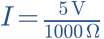
Convert 1 kΩ to Ω and calculate I.
Hint
I = U/R; 1 kΩ = 1000 Ω.
Answer and working
Calculation notes


How much power does R1 dissipate?
Hint
P = U × I. Use amperes for current.
Answer and working
Calculation notes


Imagine doubling R1 to 2 kΩ. What happens? Check the model.
Hint
The source keeps U constant.
Answer and working
Calculation notes


At fixed voltage, doubling resistance halves current and power.
Think it through before opening the answer. Always write the formula, substituted values and units.
The mental picture
Picture a closed water circuit: a pump creates a pressure difference and a restriction limits the flow. Voltage corresponds to the pressure difference and current to flow rate. The analogy helps explain relationships; electrons are not drops of water that must travel all the way from the supply before a lamp responds.
The principle
Voltage U is measured between two points in volts. Current I flows through a branch and is measured in amperes. A voltmeter therefore connects across the relevant points, while a current meter is inserted into a branch. Resistance R links the quantities for an ohmic load.
Try it yourself
Voltage & current
Double voltage at fixed resistance. Current doubles and power quadruples. Then double the resistance: which quantities decrease?
Model limits: Ideal DC voltage source and temperature-independent ohmic resistor. No current limit, wire resistance or contact resistance.
A worked example
5 V across 1 000 Ω gives 0.005 A, or 5 mA. The resistor dissipates 0.025 W. At 10 V the figures become 10 mA and 0.1 W. A supply does not force its labelled maximum current through every connected part.
A closer look · equations and assumptions
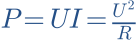

Current is the rate of change of charge: I = dQ/dt. Voltage is energy per unit charge: 1 V = 1 J/C. A real supply has internal resistance and a current limit. At a limit its output voltage may fall, so a constant-source assumption no longer holds.
A common pitfall. A current range connected directly across a voltage source is nearly a short circuit. Start with low voltage and current limiting; check the meter sockets and measurement mode before connecting.
Workshop takeaway
First ask: where is the voltage applied, and along which path does current flow? Keeping those questions separate catches many mistakes before soldering.
Sources & transparency
Original illustrations and educational calculations. No measurements of a specific product. Edited 11 October 2026.
Work it out · answers unfold
Write down your prediction first, then your calculation. Open the answer only when you are ready to compare.
01 · An ideal 6 V source supplies 300 Ω. Mark conventional current direction and find I.
Show worked answer
- Outside the source: positive to negative.
- Divide voltage by resistance.
- I = 20 mA.

02 · Convert 0.004 A to mA and 4.7 kΩ to Ω. Why use consistent units?
Show worked answer
- Milli means one thousandth: 4 mA.
- Kilo means one thousand: 4700 Ω.
- Convert units before substitution.

03 · A 470 Ω resistor has 9 V across it. Find current and dissipation. Is 0.125 W sufficient?
Show worked answer
- I = 9/470 = 19.15 mA.
- P = 81/470 = 0.172 W.
- 0.125 W is insufficient; choose a rating with margin.

04 · 220 Ω and 330 Ω are in series across 11 V. Find total resistance and current.
Show worked answer
- Add series resistors: 550 Ω.
- Both carry the same current.
- 11 V / 550 Ω = 20 mA.
