
RC low-pass: measure across C
Across which component is output measured?
Hint
Follow M and B.
Answer and working
Across C1. Choosing this output makes the arrangement a low-pass filter.
What do you expect at very low frequency?
Hint
Capacitive reactance rises as frequency falls.
Answer and working
Almost the full input appears across C1: Uout approaches 1 V peak.
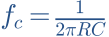
Calculate cutoff frequency.
Hint
100 nF = 0.0000001 F; fc = 1/(2πRC).
Answer and working
Calculation notes


What are output amplitude and phase at fc?
Hint
Magnitude is 1/√2; a low-pass has negative phase.
Answer and working
Calculation notes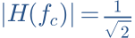


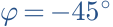
The voltage is not half of the input here.
Double C1. Where does fc move? Check the filter model.
Hint
fc is inversely proportional to C.
Answer and working
Calculation notes


This calculation assumes no additional output load.
Think it through before opening the answer. Always write the formula, substituted values and units.
The mental picture
Two people can swing equally fast and equally high without reaching the top at the same instant. Repetition rate corresponds to frequency, height to amplitude and timing offset to phase. Audio is usually more complex than a single regular swing.
The principle
At 100 Hz a signal repeats one hundred times per second; one period takes 10 ms. Peak voltage is the maximum excursion from zero. RMS voltage gives the same average heating in a resistor as the corresponding DC voltage.
Try it yourself
AC voltage, frequency & phase
Set a phase shift of 180°. The two curves are inverted relative to each other. Then increase only frequency: the angle stays the same, but the corresponding time offset becomes smaller.
Model limits: Two pure sines of equal amplitude and frequency. The time axis automatically shows two periods. No harmonics or noise.
A worked example
A sine with a 5 V peak has about 3.54 V RMS. At 100 Hz, 90° is a quarter-period, or 2.5 ms. At 1 kHz it is only 0.25 ms. A fixed delay is therefore not a fixed phase angle across all frequencies.
A closer look · equations and assumptions




The general RMS value is the square root of the mean of u²(t). The factor 1/√2 applies only to a sine. A symmetrical square wave has a higher RMS value at the same peak. Signal delay corresponds to negative phase; positive φ here makes curve B lead.
A common pitfall. A 180° shift at one frequency does not automatically mean reversed wiring. Reversing polarity changes the sign at every frequency; delay produces a frequency-dependent angle.
Workshop takeaway
Label every voltage as peak or RMS. Whenever you discuss phase, include the frequency.
Sources & transparency
Original illustrations and educational calculations. No measurements of a specific product. Edited 11 October 2026.
Work it out · answers unfold
Write down your prediction first, then your calculation. Open the answer only when you are ready to compare.
05 · Oscilloscope: 2 V per division; sine spans 3 divisions peak-to-peak. Find peak-to-peak and peak voltage.
Show worked answer
- Peak-to-peak = 2 · 3 = 6 V.
- For a symmetrical sine, peak is half that.
- Peak voltage: 3 V.

06 · Find RMS voltage of the sine in task 5, with no DC offset.
Show worked answer
- Divide peak by √2.
- 3/√2.
- RMS = 2.121 V.

07 · Timebase 0.2 ms per division; one cycle spans 5 divisions. Find frequency.
Show worked answer
- Period = 5 · 0.2 ms = 1 ms.
- Frequency = 1/period.
- Frequency = 1 kHz.

08 · Two 1 kHz sine waves are offset by 0.25 ms. Find phase-difference magnitude.
Show worked answer
- Period = 1 ms.
- Offset is one quarter cycle.
- Phase magnitude = 90°.
